3 Pin Map Sensor Wiring Diagram – It utilizes two discs of copper clad board with a piece of foam in between for each of 64 sensors. As the foam gets compressed, the capacitance between the two pieces of copper changes . I did it with 3-electrode electrochemical gas sensor. Now I am working with 4-electrode electrochemical gas sensor how can I connect that with LMP91000 without external circuitary? Circuit diagram .
3 Pin Map Sensor Wiring Diagram
Source : www.acadiaforum.net
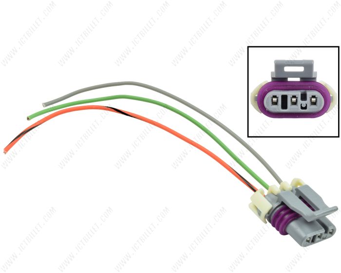
LS 3 Wire Gen 3 MAP Sensor Manifold Absolute Pressure Connector
Source : www.ictbillet.com
MAP Sensor Wiring | Team Integra Forums
Source : www.team-integra.net
Alky kit with Dpe map sensor? CorvetteForum Chevrolet Corvette
Source : www.corvetteforum.com
MicroSquirt® Introduction
Source : www.useasydocs.com
GM 3 bar map sensor calibration G4+ Forums | Link Engine
Source : forums.linkecu.com
Toyota map sensor pinout
Source : in.pinterest.com
3 Bar Map Sensor Wiring Camaro5 Chevy Camaro Forum / Camaro ZL1
Source : www.camaro5.com
Technical Friend | Srinagar
Source : www.facebook.com
MAP Sensor Wiring Diagram: Learn How to Connect Your Car Sensor
Source : www.tiktok.com
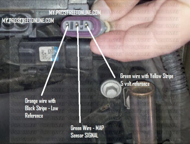
3 Pin Map Sensor Wiring Diagram MAP Sensor wiring colors | GMC Acadia Forum: A five-wire oxygen sensor is considered a wideband sensor. Traditional oxygen sensors have only one or three wires. The five-wire system allows the sensor to process more information, in turn creating . A ladder diagram consists of two vertical rails that represent the power supply, and horizontal rungs that contain the logic elements. The logic elements can be contacts, coils, timers, counters .


